DØ Run IIb L1Cal EM Algorithm
updated: 21-Jul-05
Index
-
An illustration of the algorithm
-
Description of the Chosen Algorithm
-
Comparison of various EM algo
firmware implementations
-
Algorithm Studies
(DØNote 4663), S.Lammers and G.Pawloski
-
EM Isolation and EM/HAD Fraction
information are included as an
extra output bit for each of the 16 EM objects in a SW chip.
-
The SW chip output is expanded to include the
Isolation/EM-Fraction information using spare lines.
-
The TAB-to-GAB output also changes to
accomodate the isolation information.
-
Examples of the use
of Isolation in the And/Or terms
-
Here are a list of aspects of the algorithm
about which may not be obvious and lead to limitations in it use
-
Numbering
Convention
for data in Sliding Windows Chips.
Note: each cell in the grid is can also be referenced by its
(eta,phi) coordinates within the chip.
-
Older EM Algorithm proposals
Algorithm Illustration
Chosen EM Algorithm: Algo 4 - (1,1,x) w/ H or V
Nearest Neighbors
The best algorithm we have found so far is rather different in
structure from the "atlas algorithm" but should return essentially
the same results. It returns Et in either a "horizontal" (2 TTs in
eta) or "vertical" (2 TTs in phi) cluster with one of the two TTs
corresponding to a LM as described below.
Vertical: 1x2 cluster or
Horizontal: 2x1 cluster
The algorithm consists of the following steps, most of which
are done in parallel in the firmware.
-
Find LMs using the 3x3 grid of single EM TT's as input. The LM
finding is thus of the form (1,1,x).
-
Find the maximum "nearest neigbor" TT.
This determines whether the LM corresponds to a Horizontal (H) or
Vertical (V) cluster.

-
Veto pathological topologies. An example is shown below.
-
Assign energy each LM grid point:
| 0 | if this point is not a surviving LM |
| Et(H) | if Et(H-ROI) >= Et(V-ROI) at this point |
| Et(V) | if Et(V-ROI) > Et(H-ROI) at this point |
Detailed Documentation |
pdf |
doc
see also talk by G.Pawloski at
31-May-05 meeting
|
Non-Vetoed Pathologies |
none found so far |
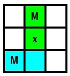
Smallest Separation of LMs
Local Maxima (LM) can be found in two contiguous 2x2 base ROIs.
In the diagrams below the following conventions are used.
- The data seen by a single Sliding Windows chip is shown on a grid.
- The main LM is shown in yellow, with its labeling TT marked with
an "x".
- The TTs used in the 2x2 base ROI are marked with an "r".
- The TTs required to find the LM are marked with an "o"
(unless this has been overwritten with an r or x).
- Some of the nearest possible adjacent LMs are shown in cyan.
| Vertical LM |
^
|
|
phi
|
08 |
|
|
|
|
|
|
|
|
|
| 07 |
|
|
|
|
|
|
|
|
|
| 06 |
|
|
|
r |
r |
|
|
|
|
| 05 |
|
|
o |
x |
o |
|
|
|
|
| 04 |
|
r |
r |
r |
r |
r |
r |
|
|
| 03 |
|
x |
r |
x |
r |
x |
r |
|
|
| 02 |
|
|
o |
r |
r |
|
|
|
|
| 01 |
|
|
|
x |
r |
|
|
|
|
| 00 |
|
|
|
|
|
|
|
|
|
| |
|
00 |
01 |
02 |
03 |
04 |
05 |
06 |
07 |
08 |
| |
|
eta --> |
| Horizontal LM |
^
|
|
phi
|
08 |
|
|
|
|
|
|
|
|
|
| 07 |
|
|
|
|
|
|
|
|
|
| 06 |
|
|
|
r |
r |
|
|
|
|
| 05 |
|
|
o |
x |
r |
|
|
|
|
| 04 |
|
r |
r |
r |
r |
r |
r |
|
|
| 03 |
|
x |
r |
x |
r |
x |
r |
|
|
| 02 |
|
|
o |
r |
r |
|
|
|
|
| 01 |
|
|
|
x |
r |
|
|
|
|
| 00 |
|
|
|
|
|
|
|
|
| |
|
00 |
01 |
02 |
03 |
04 |
05 |
06 |
07 |
08 |
| |
|
eta --> |
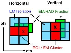
EM-Isolation and EM/HAD Fraction
EM Isolation and the EM/HAD fraction is also calculated for horizontal
and vertical ROIs.
EM Isolation
Isolation is calculated using EM TTs on either side of the ROI as
illustrated below.
- The ROI TTs are marked in yellow.
- The TTs used for isolation are marked in cyan and labeled by
numbers.
^
|
|
phi |
04 |
|
|
|
|
|
|
|
|
|
| 03 |
2 |
o |
4 |
|
|
|
3 |
4 |
|
| 02 |
1 |
x |
3 |
|
|
|
x |
o |
|
| 01 |
|
|
|
|
|
|
1 |
2 |
|
| 00 |
|
|
|
|
|
|
|
|
|
| |
00 |
01 |
02 |
03 |
04 |
05 |
06 |
07 |
08 |
| eta --> |
The cut used is: Et(ROI) > 2a Sum(1+2+3+4)
o a is a downloadable parameter - possible values are: 1,2,3 or 4
o only one value of a is allowed for the entire calorimeter
and all thresholds
o the EM isolation test can be disabled by a downloadable parameter
EM/HAD Fraction
The EM/HAD fraction is calculated using the 1x2 or 2x1 HAD TTs
directly behind a vertical or horizontal EM ROI.
- EM TTs used in the ROI are marked with "x" and "o".
- HAD TTs used in the calculation of the HAD region are marked in
red and are directly behind the EM TTs.
^
|
|
phi |
04 |
|
|
|
|
|
|
|
|
|
| 03 |
|
o |
|
|
|
|
|
|
|
| 02 |
|
x |
|
|
|
|
x |
o |
|
| 01 |
|
|
|
|
|
|
|
|
|
| 00 |
|
|
|
|
|
|
|
|
|
| |
00 |
01 |
02 |
03 |
04 |
05 |
06 |
07 |
08 |
| eta --> |
The cuts used are:
o Vertical:
Et(1x2) > 2b HAD(1x2)
o Horizontal: Et(2x1) > 2b HAD(2x1)
o b is a downloadable parameter - possible values are: 1,2,3 or 4
o only one value of b is allowed for the entire calorimeter
and all thresholds
o the EM/Had fraction test can be disabled by a downloadable parameter
Constructing the SW Chip Output
The new SW chip output
format is shown here.
Briefly, a 3-bit word is used,
for each of the 4x4 EM objects sent out from a SW chip,
to indicate the highest threshold that was passed by that object.
Consequences of this scheme are described
here
In the new scheme, each of the 16 EM objects sent out by the SW chips
has two types of output words associated with it.
-
3 bits:
The highest of 7 Et thresholds passed by the object, without any
requirements on EM-Isolation or EM/HAD fraction.
This information is passed in the currently existing EM words.
-
1 bit:
The AND of EM-Isolation and EM/HAD-Fraction cuts on each object
described above.
This information is passed as 16 bits in the spare lines.
Constructing the TAB Output
Because of the new EM-Isolation bits, the TAB output has to change as
well.
The new TAB output is
shown here.
The new algorithm will pack one of the spare TAB-to-GAB lines with
Isolation bits. For each eta-region sent out of the TAB (S,N,C) and
for each phi (2,3,4,5) the corresponding bit in the output word will
be set if any EM object in that eta-region passes the
EM-Isolation and EM/HAD-Fraction cuts.
The EM information output from the TAB is then.
-
12, 12-bit words: (phi=2,3,4,5 x eta=S,C,N).
Each word contains six 2-bit counts of the number of EM objects
that are found at for each of 6 Et thresholds (no isolation
requirement) in that phi,eta-region.
-
3, 12-bit (4b used) words: (eta=S,C,N)
Each word uses 1 bit (0-3) for each of the four phi's in the
eta-region considered. That bit is 1 if there is
any EM object in the eta,phi-region
that passes the EM-Isolation and EM/HAD-Fraction cuts.
Limitations in the Above Specification
Thresholds
Issues related to the thresholds are discussed
here.
In this scheme, Et and isolation information are
separate. There are thus no problems related to the fact that
we send only the highest threshold passed from the SW chips to the
Global chip on the TAB.
Threshold usage is summarized below.
| Type |
Thresholds avail inside TAB |
Thresholds avail inside GAB |
| Et Information |
7
sent as highest threshold passed for each object in TAB
|
6
sent as 2-bit counts at each phi=0-31 for eta-regions=S,C,N
|
| Isolation & EM-Fraction |
1
1 criterion for all Et thresholds for each EM object in TAB
|
1
1 criterion for all Et thresholds ORed over all EM obects
in the eta-region, for each phi=0-31
|
Single TT Algorithm
A single TT EM algorithm is not included in the current firmware.
If it should prove necessary to include triggers based on single
TTs into the EM list a separate, special-purpose firmware file would
have to be created. This would require a substantial amount of work.
A description of such an algorithm can be found
here.