
General
RunIIb Trigger
Documents
Meetings
Data
Installation
Design
Hardware
Algorithms
Columbia
MSU
Saclay
UIC
Run IIa
L1Cal
Framework
DØ Run 2b L1Cal
Sliding Windows Algorithms
| Introduction | LM Finding | Thresholds |
| EM Algo | Jet Algo | Tau Algo |
| Firmware | ||

Last updated: 07-Oct-05
Introduction
Implementation of the Sliding Windows algorithms run in the TABs consist of three basic steps.
- Construction of Regions of Interest (ROIs) containing sums of contiguous TTs
- Finding Local Maxima (LMs) in the grid of ROIs.
- Constructing Objects (EM, Jet, Tau) for found LMs.
-
x (roi_size)
= the size of the ROI in TTs in eta & phi.
If these sizes are different, then two numbers are used. - y (lm_sep) = the minimum separation (in TTs) between the left/upper edge of ROI A and the right/lower ROI B if A and B are to correspond to two LMs.
-
z (ring)
= the size of the ring (in TTs) around an LM used for:
- additional energy added to the ROI to form a Jet
- isolation for EM and Tau objects.
- ROIs are 2x2 in eta x phi
- ROIs must be separated by at least 1 TT to be separate LMs.
- The ring size for Jet sums and EM, Tau isolation is 1 TT in eta and phi
- ROIs of 3x3 in eta x phi
- ROIs corresponding to two LMs can touch each other
- Ring size of 1.
- ROIs of 1x2 in eta x phi
- The edges ROIs corresponding to two LMs must be separated by at least 1 TT.
- Ring size of 1.
Local Maxima Finding
TT Input Grid
TTs are arranged in a grid of 40 x 32 in eta x phi.- eta = 0...39 - but only 2...37 are used in LM finding, etc.
(eta = 0,1,38,39 correspond to the ICR) - phi = 0...31
ROI Grid
ROIs are labeled using the following scheme.- roi_size = odd: use the center TT of the ROI
- roi_size = even: use the TT just to the left/below the center point of the ROI.
LM Grid
Because ROIs can have size >1 and because we generally require some separation between LMs, LMs cannot be constructed for all eta points. This is not the case for phi because it forms a cylinder with phi=31 physically adjacent to phi=0.Examples of these and other limits are shown in the table below and illustrated here.
| Pictures | Algorithm | ||
| Value | 2,1,1 | 3,0,1 | 12,1,1 |
| ROI start,end (eta) | 2,36 | 3,36 | 2,37 |
| ROI start,end (phi) | 0,31 | 0,31 | 0,31 |
| LM start,end (eta) | 4,34 | 5,34 | 3,36 |
| LM start,end (phi) | 0,31 | 0,31 | 0,31 |
| TT Range for 1 LM (etaxphi) | 6x6 | 7x7 | 3x6 |
| ROI Range for 1 LM (etaxphi) | 5x5 | 5x5 | 3x5 |
Finding Unique LMs
Since an energy deposit in a single TT gives multiple ROIs (they share TTs) a method of distinguishing a single LM from these ROIs is necessary. The method chosen is shown below for the 2,1,1 and 2,0,1 algorithms. In the figures below, the yellow square (x) represents the ROI that is a candidate LM. It's Et is compared to those of the ROIs surrounding it. In order to return a single LM for cases where several ROIs have the same Et, a pattern of ">'s" and ">='s" must be used, where:- > means Et(x) must be > Et(roi) for x to be a LM
- >= means Et(x) must be >= Et(roi) for x to be a LM
| 2,1,1 Algorithms | 2,0,1 Algorithms |
 |
 |
This method works well for algorithms with even roi_size, but produces
offsets and some pathologies for odd roi_sizes. This is illustrated
here.
Thresholds
Each of the 16 Jet, EM and Tau objects that are produced by a single SW chip is output as a 3-bit number indicating the highest threshold that the object has passed. These thresholds are meant mainly to be based on the Et of the object, but could have other components: an isolation cut that varies with energy for example.Details and Consequences
-
An object is assigned to threshold i if:
-
Et(object) > Et(threshold-i)
-
7 thresholds (1-7) are used in the TAB.
Output=0 is used to indicate that no thresholds were passed. -
Information about the highest 6 of these thresholds are
sent from the TAB to the GAB.
All 7 thresholds are sent to L1CalTrack. - The construction of L1Cal And/Or terms in the GAB as well as the interpretation of Object data in the Cal-Track and L2 systems assumes that the events passing threshold i+1 are a subset of the events passing threshold i. Thus an output word of 4 will be interpreted as having fired thresholds 4,3,2,1 - even if one of the low thresholds did not actually pass.
- If the above is not the case, then triggers depending on threshold i also depend on whether threshold i+1 fired as well. This may turn out to be a small effect, but it should be kept in mind.
Examples
As an example consider a 2-threshold trigger (more precisely, these should be called cluster categories).- Thresh-1: Et > 4 GeV & EM(ROI) > 4*Iso(reg)
- Thresh-2: Et > 6 GeV
- Thresh-1: [Et > 4 GeV & EM(ROI) > 4*Iso(reg)]
OR [Et > 6 GeV]
Possibilities
If different algorithms (e.g. different isolation cuts) are used for different Et thresholds then there are several possible ways to deal with the output.-
Separate Et and Isolation Information (default)
EM Isolation information is passed as a separate bit from the Et threshold. This avoids all the problems described above. -
Inclusive Thresholds:
- out[2..0] = 0 ==> no threshold passed
- out[2..0] = 1,2 ==> highest thresh passed from Algo-1
- out[2..0] = 3-7 ==> highest thresh passed from Algo-2
-
Exclusive Thresholds:
- out[2..0] = 0 ==> no threshold passed
- out[0] = 1 ==> passed Algo-1 thresh
- out[1..0] = 1,2,3 ==> highest thresh passed from Algo-2
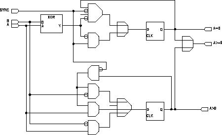
Details of Algo Implementation in Firmware
- Bit-Serial Arithmetic
All arithmetic in the hardware is performed bit serially on 12-bit data streams. Block diagrams of the implementation of various operations are given below. - Divides in the Tau Algorithm
- Sin & Cos in the Et(miss) Algorithm